08 Jul

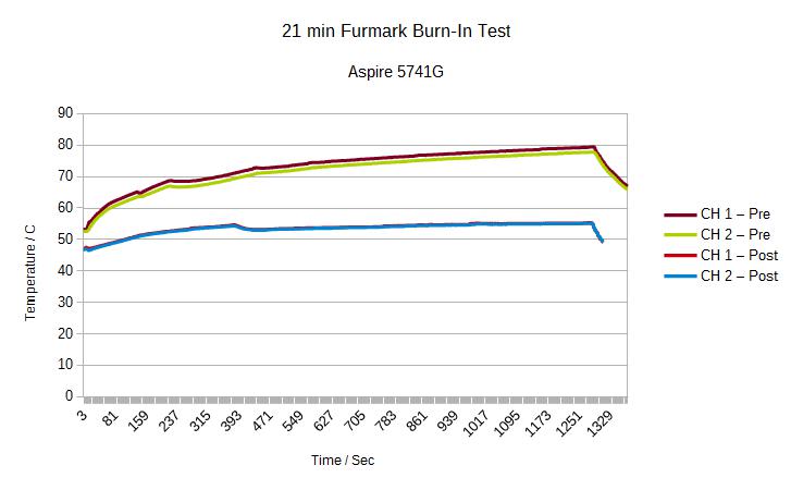
Height probe for CNC-machine [Part I]

Our computer aided work horse, customized Shapeoko2 milling machine, is working well. Yet, we have been able to make pcbs with pretty good results but also wood carving. After clearing the machine from all that glassfiber and wood dust we are ready to add new feature to the machine.

Small bumps for machine, one giant fail end result

While your milling machine is top notched and tuned for accuracy, your work piece might not. Not even close. A piece of plain copper pcb is not flat. There is easily +- .1 to +- .2 mm height differencies on the board(warpage etc.). It does not sound much and is not a real problem with flat head tools, but if you aim to say 12 mils (.3 mm) with a V-carve tool working its way at 0.23 mm deep,  you see the point.

Copper board bumps are small, even tiny, compared to downs and hills on surface of wood where scale is millimeters. Again, it really depends your output if that matters. However, carving with your precious milling tool 1 mm deep on one side of the wood and suddenly you hear (and smell) a failure and see your tools stalling at 5 mm deep on other side and that 3 mm safety height (machine's travelling height) you set up was no way near enough.

IMG_20160706_110901

What the hell! My eyes told me this is a flat piece of wood!


Computer aided height probing

So how do you deal with those quirks on a copper board. Well, you can take your blacksmith hammer and forge it to flat but we bet it's not a good idea. Most CNC-softwares, like Chilipeppr which we like to use, have height probing capability. It forms a matrix of probing points of your choise and modifies your g-code so that height differencies are taking care of.

Probing hardware setup for pcb copper board is simple by using the Zmin input of tinyg board (CNC-controller board installed in our Shapeoko2). Grounding the pcb board by soldering the wire on copper board and connecting the other end of the wire on tinyg ground while Zmin input connects to milling tool. Now there will be a loop when milling tool touches the board. This is how we have done it and after couple of broken tools works like charm.

This setup not going to work with non-conductive materials like wood. We need new kind of probing sensor.

Proximity sensor

When it comes to mechanical sensor, first in mind is a simple limit switch. It would be easy to handle and cheap but needs serious fixing accessories aside. More off-the-shelf solution is ready-made touch probe with proximity (inductive) sensor which fits out-of-box on our machine. Lets tear one apart and see what's inside.

IMG_20160706_110634

43mm CNC Digitizing Touch Probe Sensor


Touch probe comes with 4 tips, 2 with V-shape and 2 with ball tip. Proximity sensor (TS12-02N-2) is baked (screwed and replaceable) on upper half of sensor. Bottom half is attached to probe tip with a metal plate and finally there is a spring between halves.

proximity_sensor

Inductive proximity sensor


TS12-02N-2 is an active sensor with three color coded wires. It takes 10-30 VDC and yields same voltage with max 200mA output current via black wire. Take a look datasheet for more detailed internal schematic. This is NPN output with normally closed function. This means that while your load is connected to collector side of transistor (in this case, between black wire and brown wire) it provides input voltage over the load. Normally closed (N.C.) means that transistor is "closed" and conducting, hence connection to ground is formed.

NPN_schema

TS12-02N-2 connection


Lets see how tinyg board limit swtich inputs are formed. Synthetos claims following:

The inputs are 3.3v logic inputs and must not have 5v applied to them or you will burn out the inputs. The inputs are de-glitch filtered with a resistor-capacitor circuit (RC circuit), and pulled up to 3.3v on the board via 2.7K ohm resistors (strong pullup).

Our mechanical limit switches  for X- and Y- axis are set as N.C. Since all limit switches are required to function same way, we need N.C for Zmin limit. How N.C. works on tinyg is following. As stated, inputs are pulled high via pullup resistor. Since limits are normally closed (tied to ground), hence limit inputs are low while limits are not triggered. This means we have to provide 3.3 V logic high to Zmin input when triggered.

limit_input_schema

Limit logic input

Dividing voltage

Based on sensor's schematic, we can use the proximity sensor to drive Zmin input on tinyg board. Remember, voltage level over load is same as input voltage of the sensor and in this case will be 24 V taken from tinyg power supply. That is way too much for Zmin input to handle. This is where voltage divider circuit kicks in. Lets draw a schematic to see what we up to.

sensor_input_schema

Proximity sensor limit input schematic


So R2 is our load here, right? Lets make it big say 10K. Adding another resistor between black and blue (ground) like nice and round 2K. We then get (2/12)*24 V = 4 V on limit_input. That is a bit off from 3.3V but perfectly fine (< 5 V) for testing (we can adjust values later).

Breadboard testing

Breadboard testing


Test run shows that this setup works as indended. Voltage values are 0.71 V while not triggered, which is below low input max logic value (Can you see why 0.7 V? Hint: Diode) and still considered as logic low. When trigger voltage jumps to 4.2 V which is within 5% tolerance what we calculated.

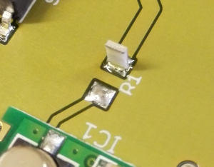
Here is voltage divider connection board. Tweaked resistor values are one 10K for R1 and 1K plus 3 x 100R plus 220R in series for R2, providing about 3.1 V trigger voltage.

Connection board with voltage divider

Connection board with voltage divider


What about auto-leveling

The proximity sensor works great as Z-limit sensor, a question is does it work on auto-leveling procedure? Answer is no and a test run verifies this. Reason is that auto-leveling has opposite function compared to N.C limit switches. As we told earlier, PCB auto-leveling is wired such that loop is normally open (ground  to tool - loop is open while there is a gap between tool and grounded PCB). To get this work on auto-leveling, we need to invert the logic but that's for part II.


01 Sep

Ebay LCR meter

LCR meter is something to consider while your lab fills up with stuff to be repaired. Particular a meter with ESR measuring capality is vital. The most common problem with any electrical device is bad cap. Visual inspection usually gives a hint of bad capacitor, more over big electrolytic capacitors have tendency to blow.

Most multimeters have capacitance measurement capability but it does not tell whole truth eg. your measurement may indicate valid value but cap may still be dead. You need to measure ESR. Good thing with most ESR meters is that you can measure ESR while the capacitor is still on circuit. This is possible because the meter does not provide as big voltage level which would light up circuit's non-passives. You may want to check your meter manual if it's suitable for on-circuit measurements.

Price range of handheld LCR meters goes from sub 100 euros to 400 euros and beyond.  Note that not all LCR meters can measure ESR. If you only need capacitance and ESR measurements, Peak Electronics has nice meter to offer (here is review made by Martin Lorton).

If you want quality and accuracy go for well-known brand. Fortunately there exits a cheap meter on the market, DER EE DE-5000, which is accurate and recommended by the hobbyists. DE-5000 also has 100kHz measurement capability which is usually offered by high-end meters (see U1733C vs. U1732C).

So we gave a green light for DE-5000 and after week or so we got this beast


DE-5000 on the right. Size comparison to Brymen multimeter.

DE-5000 on the right. Size comparison to Brymen multimeter.


Pretty much dead already

The meter came with 9 volt battery included so it was ready to take measurements... except it did not start. The battery got very hot right after it was plugged in, which indicated short circuit (no, battery was not backwards whatsoever).

Of course situation like this your first thing to do is take screwdriver and tear it... NO! As faithful customer you contact to your seller and ask for refund or new meter. And that's what we did. In this case, seller wanted to send us broken meter back so he/she could inspect it and send a new one. But before doing that we took it apart...

Now there is your problem

A product with no warranty sticker is real "please look inside me" - sign. So lets take closer look of this meter.

No visual sign of fault. Lets probe some.

No visual sign of fault. Lets probe some.

Not much inside but all you need.  Power management, LCD chip and main custom chip. Layout is neat and clean. First thing to do was to verify short circuit. No surprise here, that is ladies and gentlemen, a top-notch short-circuit.

Class A short circuit

Yep, short circuit

If you follow the red lead you instantly notice that it is connected to R4 and also parallel to (glass) a diode D5. Purpose of this diode is reverse battery protection. See, if a battery is properly placed, the diode just sits there doing nothing since PV-junction is reverse biased; no current flows through it. Shit happens when the battery is reversed, the diode wakes up and let all the current flow through it, hopefully protecting rest of the circuit and eating your battery in a blink of an eye. Problem was, the battery getting hot even it was correctly placed (getting hot, current flows).

IMG_20150702_151813

Measuring diode D5

According to other diodes, voltage drop is about 0.5V for each diode. D5 gave something else, no matter which way measured.

IMG_20150702_151754

Shitty diode.

Measurement makes sense and fits nicely into context. The diode is dead and it is shorted in every possible ways making meter useless. Changing the diode would have been easy solution indeed, but whether damage already happened to the rest of the circuit, we did not know and we did not care since we shipped it back to seller and got a new one.

Conclusion

Even with negative experience with the first candidate of the meter, it still is decent meter. The new one works great and measurements seems to meet the specs. But like we said earlier, if you want quality, go for well-known brand.


05 Dec

Bus Pirate

Bus Pirate is excellent tool for hacking and troubleshooting. I'm not go into deep details of this magnificent device since all is well documented. It is cheap and open source and you can make your own.

buspirate_mikropure

Building

We got our board a while ago from Dangerous Prototypes. It is just a bare pcb so sourcing all the parts was next thing to do. Bus Pirate uses some 0603 parts, even tough these are small yet doable by hand soldering. We did not have direct access for proper parts via our local distributors. For example instead of a TTSOP-14 package of 4066 switch we used  a SOP-14  package. It was glued and soldered using dead-bug technique (the chip is faced upside down) and hack wired into pads. Pretty fast it turned out that this is not recommended method, it was pretty hideous to solder all those wiring . We ordered and installed the right TTSOP-14 package. In picture you can see remains of "the dead bug" lurking behind a connection socket.

Another problem came ahead while testing the Bus Pirate. It did not pass all the tests, namely  powering the regulated 5V and 3V3 lines were faulty.  Regulators we were using were  MCP1804 ones from Microchip instead of listed  MCP1801. At first peek they look very same from  feature point of view. But take a look at pinouts. They do have swapped pins 3 and 4, NC (not connected) and SHDN (shutdown), respectively. SHDN is active-low and regulators are controlled by PIC providing HIGH to SHDN pin. With MCP1804, PIC is now connect to NC pin. This was easy to fix, just a bit of hack wire between NC and SHDN pins.

Flashing Firmware

Once the parts are soldered, Bus Pirate pirate is ready for duty. Or did we miss something? Body is ok but soul is missing. To bring Bus Pirate live, lets flash a firmware into it. The pcb contains a ICSP header where you can plugin your favorite programming device. We have a PICKIT 3 and that what we use.

mplab_bp

First we flash a bootloader in to Bus Pirate. This allows us to load firmware via USB using ds30 Loader. Note that FTDI drivers needs to be installed while connecting BP to USB.

Next we plugin a jumper to wake up the bootloader, fire up the ds30 Loader application and program the firmware.

ds30_bp

Now we should be able to communicate BP via console. Hitting Enter  on console screen yields a command prompt. Note that if you are using Terra Term and nothing shows up, remember to change baud rate to 115200: Setup --> Serial Port. 

console_bp

Examples

So what can you do with Bus Pirate? In first example we use BP and AVRDUDE to burn fuses of  ATmega 328P microcontroller.  Greater details can be found here. To calculate fuses we prefer this online calculator.  Here is an example of command

avrdude -c buspirate -p m328p -P COM6 -v -U lfuse:w:0x62:m -U hfuse:w:0x99:m -U efuse:w:0xFF:m -U lock:w:0xFF:m

avr_bp

For more detailed example, lets connect Bus Pirate to MCP7940M RTC and see if we can read/write something to MCP7940M's SRAM. To communicate with RTC we need I2C protocol. A schematic below shows an example of connecting Bus Pirate to the RTC.

RTC_Schema

Connect your (BP) MOSI <--> SDA (RTC), (BP) CKL <--> SCL (RTC) and (BP) GND <--> GND (RTC). You may power up the RTC from BP or what ever source you want.

Next, we start Tera Term console for I2C-terminal. In this example, we are going to write one byte to RTC's SRAM and read it back. More details can be found on datasheet  (p. 30). There are two address to remember while communicating with this  RTC. First one, 0xDE, which bus pirate also finds when using  (1)-command (see pic below) is a write address. Second one, 0xDF, is a read address (datasheet prefers these as control bytes).

bp_MCP7940M_00

SRAM starts at 0x20. To read that address first we write '[' which is I2C start bit followed by write control byte 0xDE and address 0x20. Now we have a pointer to that address. Let us write a second start bit by typing '[' followed by control byte 0xDF which indicates that we'd like to read from address 0x20. Read is done with 'r:1' which commands to read one byte. We end reading by stop bit ']'

bp_MCP7940M_01

The byte we read was 0xFF. How about writing? Writing goes same manner. First start with start bit followed by write control byte, the address where to write and a byte which will be written, i.e. 0x01. We don't need another start bit since we are already in "writing mode". We end command with stop bit:

  [0xde 0x20 0x01]

bp_MCP7940M_02If you type another reading command to 0x20 you can see that location now contains our byte 0x01. Time registers start at 0x00. There is no difference to read and write these registers. Remember, however, that time bytes are BCD-coded and some of them contains additional control bits so you need to mask those control bits and make a conversion to decimal numbers.

Improving writing/reading speed

As you may have noticed, it took a quite lot of time programming a MCU. This is not very practical for serious developing e.g. firmwares where you are constantly testing your code on MCU. You can spend your precious time finding  a solution to improve writing/reading speed. If you find one, please let us know.

However, what can you do is that you can change the hardware implementation of Bus Pirate. Instead of using  the Bus Pirate firmware,  go and change the firmware to STK500 device, which is also available inside BP firmware packet.

avr_bp_stk500

Writing at 1.9 kB/s is still kinda slow but about 60 times faster than with original BP firmware (30 Bytes/s).

22 Sep

Läppäreiden lämpöongelmat

Tietokoneen prosessorit ja näytönohjaimet tuottavat valtavasti lämpöä. Jos tätä lämpöä ei saada johdettua pois tietokoneesta, seurauksena on ennen pitkään koneen kaatuilu. Pahimmassa tapauksessa jotain saattaa hajota. Suurin ongelma, erityisesti läppäreissä, on pölyn kertyminen koneen tuulettimeen. Tässä artikkelissa näytämme, kuinka me hoidamme lämpöongelmaisen läppärin.

laptop-dust2

Pölykertymä tuulettimen ritilässä

x86-arkkitehtuurin (tuttavallisemmin Windows/Linux) kannettavien lämmönsäätely on toteutettu lämpöjohtavan putken ja tuulettimen yhdistelmänä. Pölyn kertyminen tuulettimen ritilän sisäpintaan on tyypillinen lämpöongelmien aiheuttaja. Pölyn siivoaminen vaatii siis koneen avaamisen. Samassa on hyödyllistä vaihtaa myös lämpötahnat prosessori- ja näytönohjain-piiriin. Piirit ja jäähdytinputki on puhdistettava huolellisesti vanhasta tahnasta. Välineillä, kuten ArcticClean, mikrokuituliina ja vanupuikot, puhdistus onnistuu helposti.

laptop-heatpipes

Vanha lämpötahna on puhdistettava ennen uuden lisäämistä

Uutta lämpötahnaa ei tarvita paljoa. Herneen kokoinen tippa piirille on enemmän kuin tarpeeksi.

clean-core

Puhdistettu piiri

Ennen ja jälkeen puhdistusoperaatiota suoritetaan lämpörasitustesti Furmark-ohjelmalla. Furmark kuormittaa läppärin näytönohjaimen ja prosessorin maksimaalisen lämmön tuottamiseksi. Lämpögraafit saadaan K-tyypin mittausantureilla koneen sisältä, prosessorilta (CH1) ja näytönohjainpiiriltä (CH2). Mittalaitteena toimii Amprobe TMD-56.

aspire

K-tyypin termoparit asennutetuna mittausta varten

Lämpögraafista nähdään puhdistusoperaation teho; ero on huikea.

aspire_5741g_furmark_21min_test

Esimerkkikoneen 21 minuutin lämpörasitustesti ennen ja jälkeen puhdistuksen. VAROITUS: Prosessorin lämpötilan ylittäessa +70C liikutaan jo vaarallisilla vesillä ja testin keskeyttämistä on syytä harkita.


29 Aug

Tekniikka 2014 trade show

Tekniikka_logo_2014.fh11

Annual trade show, Tekniikka 2014,  for automation and manufacturing professionals will be held on 3. - 5.9.2014 at Jyväskylä Paviljonki. Also, there is security trade shows at the same time so you don't want to miss it this year . We won't be there but our good mate Protopaja Kalliokoski will be. Go check out their booth at B202.

20 Jul

Tombstone effect

Tombstone effect is when smt passive chip, usually resistor or capacitor, raises from another end yielding non-contact junction on lifted side of a pad. This happens especially with rework station while you heat the pads unequally. While reflow stage happens on another end, torque at that end lift ups the passive. This is how it looks like, a classic tomb stoning.

tombstone_resistor

However,  tombstone effect can be barely visible yielding faulty circuit, something to be aware if you are soldering smt components with a rework station.

Tombstone effect can happen another axis too. Instead of raising another end, passive component can rotate aside from the pad. Here is an example of rotated ferrite bead.

tombstone_bead

Tomb stoning can problem even with reflow ovens. Here is some variables to watch out.